In transformer manufacturing, the method of core lamination assembly is a key determinant of overall performance. The joint design used in stacking grain-oriented electrical steel (GOES) or non-oriented steel sheets directly affects transformer losses, efficiency, and operational reliability. This article offers a comprehensive review of the most common joint configurations, analyzing how joint structure influences magnetic properties, production complexity, and energy efficiency compliance.
Fundamentals of Transformer Core Lamination
Geometric vs. Effective Cross-sectional Area
The geometric area refers to the theoretical cross-sectional size of the core, whereas the effective area accounts for gaps between steel laminations and insulation coating thickness. A larger effective area ensures more uniform flux distribution and reduced core losses. Thus, maximizing the effective area is crucial during design and assembly.
Lamination Factor and Flux Density
The lamination factor (typically between 0.91 and 0.96 for 0.35 mm steel) is the ratio of effective area to geometric area, indicating how tightly the core is stacked. A higher lamination factor leads to better magnetic uniformity and lower core loss.
Fill Factor
This refers to the ratio of the actual magnetic cross-section of the core column to its enclosing circle. Higher fill factors improve space utilization but increase manufacturing complexity, requiring careful trade-offs between efficiency and cost.
 Multi-step step-lap configurations, including versions with integrated oil ducts.
Three Common Joint Types and Magnetic Performance
Butt Joint
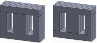
The earliest joint method, where steel laminations are stacked vertically in a straightforward end-to-end fashion. While simple and structurally robust, it’s unsuitable for cold-rolled grain-oriented steel (CRGO) as it causes flux discontinuities at the joint, increasing no-load loss. Suitable for hot-rolled or non-oriented steels (CRNGO).
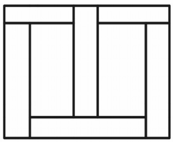 Butt Joint in Transformer Core Lamination
Step-Lap Joint
A hybrid configuration alternating between straight and 45° mitered cuts to stagger the joints. This design smooths magnetic flux transition, reducing localized heating and acoustic noise while improving steel usage. Step-lap joints are widely adopted in distribution transformers and support high production efficiency when integrated with CNC cutting and auto-stacking platforms.
MOOPEC offers extensive expertise in step-lap lamination for efficient, quality production.
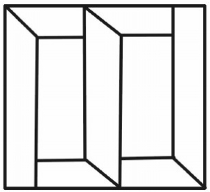 Step-Lap Joint in Transformer Core Lamination
Mitred Joint
All joints are angled to align with the rolling direction of CRGO steel, minimizing core losses and enhancing flux continuity. This high-performance joint suits large, low-noise, high-efficiency transformers but requires precise cutting, deburring, and stacking techniques.
Manufacturers seeking to combine mitred joints with high-grade CRGO (e.g., M20MQ70)can benefit from customized solutions provided by MOOPEC.
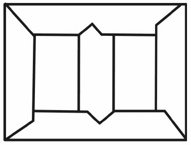 Fully Mitred Joint in Transformer Core Lamination
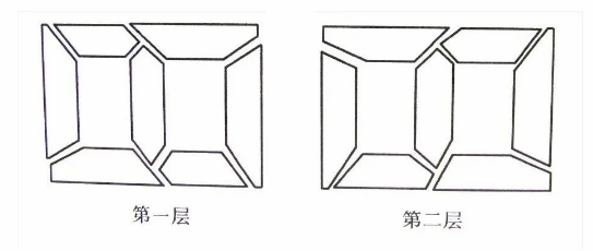 The core lamination shape diagram is drawn based on the core stacking drawing, as shown in Figure 4.

Figure4 Core Lamination Diagram
A Core Stacking Diagram; B Lamination Shape Diagram
Magnetic Performance Comparison by Joint Type
| Joint Type | Core Loss | Noise | Flux Continuity | Processing Complexity |
| Butt Joint | High | High | Poor | Low |
| Step-Lap | Medium | Medium | Good | Medium |
| Mitred Joint | Low | Low | Excellent | High |
Material Compatibility and Joint Design Logic
CRGO Steel: Due to strong grain orientation, step-lap or mitred joints are recommended.
Hot-Rolled Steel: Uniform magnetic properties allow for butt joints.
High-Grade CRGO (e.g., M20MQ70): Best matched with mitred joints to achieve low P1.7/50 loss values.
Manufacturing & Equipment Requirements
Step-Lap: Requires precise alignment and CNC shearing; often used with automated stacking platforms.
Mitred: Demands exact cutting angles, minimal edge burrs; laser cutting and visual alignment systems are preferred.
Automation: The rise of industrial automation enables scalable production of both step-lap and mitred cores.
Standards and Testing Methods
IEC 60404-2: Standard for magnetic and core loss testing of electrical steel.
GB/T 2521: Chinese standard for steel testing.
ASTM A343: Common US standard for alternating magnetic flux measurement.
Infrared Imaging & Flux Scanning: Used to detect hot spots and magnetic distortions at joints.
Emerging Trends and Technologies
Multi-level Step-Lap: Advanced 8-layer designs that optimize magnetic pathways.
Domain Refinement: Reduces core loss further, especially in mitred joints.
Robotic Lamination: Enhances consistency and automation in assembly.
Eco-Friendly Ultra-Thin Steel: Combined with precision mitred cuts to improve energy grades.
Conclusion: A Balance Between Design and Feasibility
Transformer core joint design is a delicate balance between achieving superior magnetic performance and maintaining manufacturability. When selecting the optimal configuration, engineers must consider material type, transformer size, voltage class, efficiency goals, and production capacity. As the industry pushes toward greener energy and smart manufacturing, joint designs that enable lower losses, higher automation, and scalable efficiency will dominate future core assembly trends.
MOOPEC – Your Partner in High-Performance Transformer Cores
MOOPEC is a technology-driven provider of electrical steel and core lamination services, offering end-to-end “coil-to-core” solutions tailored for transformer and motor manufacturers.
Our capabilities include:
Material sourcing for CRGO/CRNGO with multi-currency, small-batch trade support
Product Specifications
Nominal Thickness(mm) | MOOPEC | Theoretical density (KG/dm³) | Min. Induction(T) | Min.Lamination factor(%) |
| 0.20 | M20G65 | 7.65 | 1.89 | 95.0 |
| 0.20 | M20G70 | 7.65 | 1.89 | 95.0 |
| 0.20 | M20G75 | 7.65 | 1.90 | 95.0 |
| 0.20 | M20G80 | 7.65 | 1.90 | 95.0 |
| 0.23 | M23G75 | 7.65 | 1.89 | 95.5 |
| 0.23 | M23G80 | 7.65 | 1.88 | 95.5 |
| 0.23 | M23G85 | 7.65 | 1.86 | 95.5 |
| 0.23 | M23G90 | 7.65 | 1.90 | 95.5 |
| 0.23 | M23G95 | 7.65 | 1.89 | 95.5 |
| 0.23 | M23G100 | 7.65 | 1.89 | 95.5 |
| 0.27 | M27G90 | 7.65 | 1.90 | 96.0 |
| 0.27 | M27G95 | 7.65 | 1.90 | 96.0 |
| 0.27 | M27G100 | 7.65 | 1.90 | 96.0 |
| 0.27 | M27G105 | 7.65 | 1.89 | 96.0 |
| 0.27 | M27G110 | 7.65 | 1.89 | 96.0 |
| 0.27 | M27G115 | 7.65 | 1.89 | 96.0 |
| 0.27 | M27G120 | 7.65 | 1.88 | 96.0 |
| 0.30 | M30G100 | 7.65 | 1.90 | 96.5 |
| 0.30 | M30G105 | 7.65 | 1.90 | 96.5 |
| 0.30 | M30G110 | 7.65 | 1.89 | 96.5 |
| 0.30 | M30G120 | 7.65 | 1.89 | 96.5 |
International CRGO Grades
| MOOPEC Grade | POSCO | JFE | TKS | NSC |
| M20MQ65 | ||||
| M20MQ70 | H070-20 | |||
| M20MQ75 | H075-25 | |||
| M20MQ80 | 20ZH80 | |||
| M23MQ75 | H075-23 | |||
| M23MQ80 | 23PHD080 | 23JGHE080 | H080-23 | |
| M23MQ85 | 23PHD085 | 23JGHE085 | H085-23 | 23ZH85 |
| M23MQ90 | 23PHD090 | 23JGH090 | H090-23 | 23ZH90 |
| M23MQ95 | 23JGH095 | 23ZH95 | ||
| M23MQ100 | 23JGH100 | 23ZH100 | ||
| M27MQ90 | 27PHD090 | 27JGSD090 | H090-27 | 27ZH90 |
| M27MQ95 | 27PHD095 | 27JGSD095 | H095-27 | 27ZH95 |
| M27MQ100 | 27PH100 | 27JGH100 | H100-27 | 27ZH100 |
| M27MQ105 | ||||
| M27MQ110 | 27JGH110 | H110-27 | 27ZH110 | |
| M30MQ100 | 30PHD100 | H100-30 | 30ZH100 | |
| M30MQ105 | 30PH105 | 30JGH105 | H105-30 | |
| M30MQ110 | H110-30 | 30ZH110 | ||
| M30MQ120 | 30PG105 | 30JGH120 | 30ZH120 |
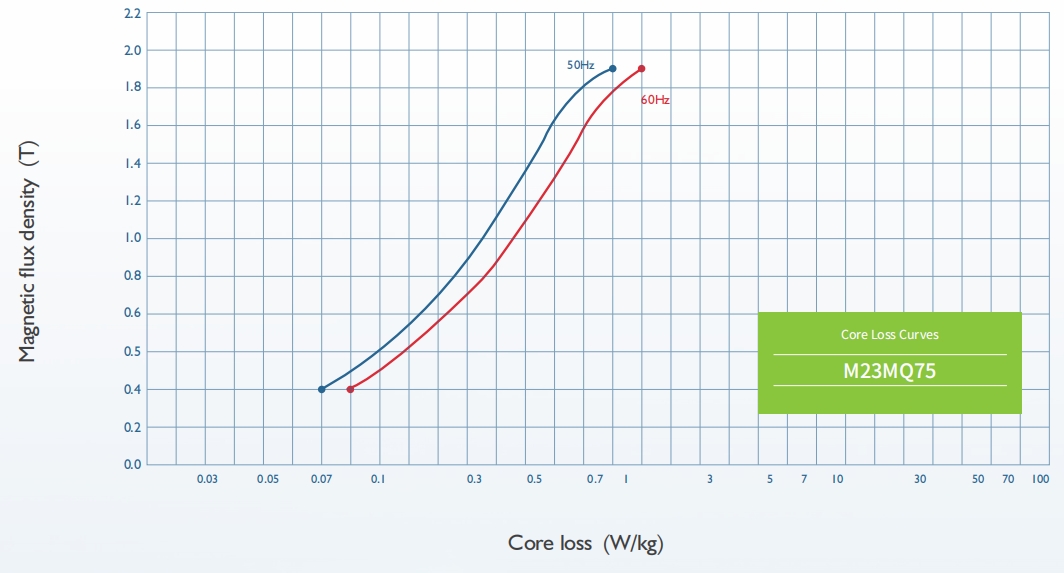
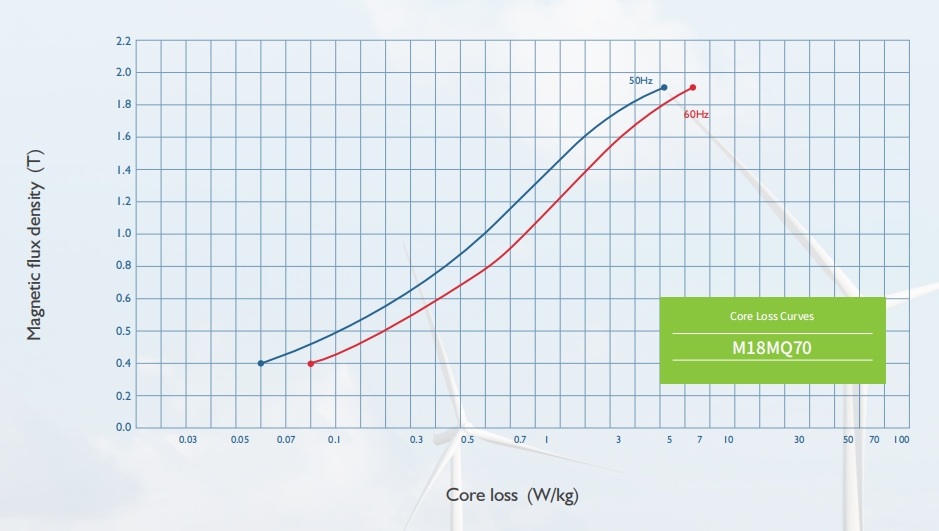
References Core Loss Curves
Applications
| Varieties | Conventional Grades | High Permeability Grades | Domain-Rened Grades |
| Large motors | √ | √ | |
| Large transformers | √ | √ | √ |
| Medium and small transformers | √ | √ | √ |
| Distributing transformers | √ | √ | |
| Voltage regulator | √ | √ | |
| Reactor and magnetic amplier | √ | √ | √ |
| IF transformer | √ | ||
| Mutual inductor | √ | √ | |
| TV transformer | √ | √ | |
| Radio transformer | √ | √ | |
| Radio broadcast transformer | √ |
Precision slitting, shearing, and professional step-lap/mitred lamination services
Based in Nantong, with advanced facilities including laser cutting and robotic stacking
Engineering support from drawing analysis to loss optimization and insulation strategies