In industrial equipment, the motor is the core component. Many people treat the motor core joining method as merely an “assembly detail.” In reality, however, it profoundly influences overall efficiency, service life, and energy consumption.
Why Are Motor Cores “Laminated in Layers”?
From Silicon Steel Strip to Laminated Core
As devices that convert electrical energy into mechanical energy, motors are widely used in industrial equipment. For example, these include electric vehicles, electric aircraft, and electric ships. Silicon steel is the most common soft magnetic material used in motor stators and rotors. It is a high-silicon (2-5.5 wt% Si) thin strip (0.2-0.65 mm) steel. Adding silicon reduces coercivity and increases resistivity in the steel. Moreover, thinner strips reduce eddy current losses under alternating magnetic fields.
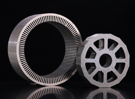
Motor stator and rotor cores are therefore constructed from hundreds of laminated silicon steel sheets. This construction minimises eddy current losses and improves efficiency. In addition, each side of the laminated core is coated with insulation to block interlayer eddy currents.
The Joining Dilemma: Strength vs. Magnetic Performance
Typically, lamination aims to ensure mechanical strength. However, joining processes may damage the insulation coating, alter microstructures, or introduce residual stress. All of these effects can degrade magnetic properties. As a result, balancing mechanical strength and magnetic performance remains a significant challenge.
Furthermore, the laminated structure of silicon steel differs from traditional overlap or butt-joint assemblies. Studying silicon steel lamination joining techniques is therefore crucial, because it accelerates the production of high-quality motors.
MOOPEC’s Role in Laminated Core Materials
MOOPEC focuses on supplying high-performance CRGO and CRNGO electrical steels for motor cores. We also offer advanced slitting, cut-to-length, and surface coating protection processes. These steps ensure the magnetic stability and low-loss characteristics of laminated structures.
Representative Core Joining Techniques
Currently, laminated core joining techniques fall into three main categories. They are bonding, mechanical fastening, and fusion welding.
1. Bonding (Similar to Gluing)
- Advantages: Does not damage insulation, low iron loss, quiet operation, good heat dissipation.
- Disadvantages: High cost, adhesives may age under high temperatures.
Because bonding offers great flexibility during manufacturing, it suits cores with complex shapes. Various adhesives are available, including organic, inorganic, and hybrid types. Once cured, adhesives provide mechanical strength and thermal conductivity. Under high load, high temperature, or high humidity conditions, however, durability remains a concern. On top of that, costs are generally higher than other joining techniques.
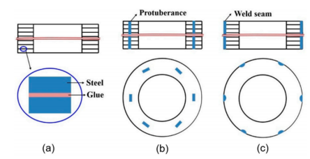
Schematic diagram of representative connection processes for laminated cores: (a) Adhesive connection (b) Mechanical connection (c) Fusion welding connection
2. Mechanical Fastening (Similar to Clamps or Rivets)
- Advantages: Simple structure, low processing cost.
- Disadvantages: Low strength, prone to loosening, magnetic performance degrades at high frequencies.
Mechanical fastening includes V-shaped clips, riveting, and locking tabs. It suits mass production of low- to medium-power motors with lower strength requirements. These methods are often integrated with stamping tools. As a result, they enable high-efficiency joining on automated production lines. However, local damage to the insulation layer at connection points can reduce magnetic performance. For this reason, mechanical fastening is often combined with other methods.
3. Fusion Welding (High-Temperature Fusion)
Laser welding is currently the most promising technology. It offers small weld seams, low residual stress, and minimal impact on magnetic properties. Consequently, it is ideal for motors with high-performance requirements, such as electric vehicle drive systems.
Unlike traditional TIG or MIG welding, laser welding produces smaller heat-affected zones and finer weld boundaries. In this way, it preserves both weld strength and magnetic properties. It is particularly suited for wound cores and precision small motors with complex structures or demanding performance requirements.
Laser Welding at MOOPEC’s Nantong Centre
Meanwhile, MOOPEC’s Nantong processing centre has introduced laser welding production lines. These lines can weld customised structures such as three-column or five-column cores. In addition, they provide end-to-end processing from material supply to lamination.
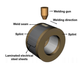 Schematic diagram of laser welding for laminated cores
Why Does Joining Method Matter So Much?
Joining the core is not just about “connecting pieces together.” Different methods affect material permeability, eddy current loss, and structural strength. Consider the following examples.
How Each Method Compares
Bonding preserves insulation, so it delivers the lowest iron loss. Over time, however, adhesives may degrade. Mechanical fasteners offer lower stability and are prone to failure during long-term operation. Laser welding is the most ideal solution, although it requires high-precision equipment.
Moreover, the joining process itself introduces residual stresses. These stresses can degrade magnetic performance under magnetic fields. Therefore, evaluating joining methods requires more than cost and process considerations. It also calls for a comprehensive analysis of their impact on electromagnetic performance.
Hybrid Approaches in Practice
In practice, hybrid approaches are often used. For example, some MOOPEC products combine bonding and laser welding. This balances performance and strength without significantly increasing costs.
New Trends: Spot Welding, Pulse Welding, and Intelligent Assembly
As the new energy sector evolves rapidly, performance requirements for motor cores are rising. Traditional large-area welding caused excessive heat, coarse grain structures, and degraded magnetic performance. Today, the industry therefore favours “pulse spot welding.” This approach uses small, high-frequency energy bursts to weld multiple points quickly with minimal impact.
Pulse Spot Welding: Where It Works Best
Research shows that spot welding performs better at low frequencies. For high-frequency applications, insulation treatments and weld density need further optimisation.
Monitoring and Control Systems
To ensure consistent weld quality, modern manufacturing now incorporates “welding monitoring and control systems.” Examples include infrared temperature sensors and welding current waveform analysis.
MOOPEC’s Intelligent Assembly Services
MOOPEC is implementing intelligent data systems for quality tracking and parameter monitoring. We also offer customised hollow core assembly services based on customer drawings. In this way, we meet the lamination needs of both standard and non-standard motor stators.
How to Evaluate Joining Quality?
Currently, evaluations focus on two main aspects.
Mechanical Testing
Torsional strength and shear tests are the standard measures, and they are carried out using specialised equipment.
Magnetic Performance Testing
Iron loss and flux density are the key indicators here, and they are assessed with standard instruments.
Advanced Research Methods
For more comprehensive data, research institutions often combine thermal analysis, finite element analysis (FEA), and digital image correlation. These tools map stress distribution and strain migration in the weld heat-affected zones. As a result, they help optimise structural design and process parameters. In addition, some studies are using thermal imaging and neutron grating techniques to further quantify weld effects. Ultimately, this work lays the groundwork for high-end equipment.
Future Trends: Smarter, More Efficient, More Flexible
Looking ahead, motor core joining techniques will evolve in four directions. First, high-frequency laser welding will gradually replace traditional methods. Second, joining processes will become smart, traceable, and predictive. Third, customised and flexible small-batch lamination manufacturing will expand. Finally, data-driven process optimisation, self-learning parameters, and real-time adjustments will become standard. All of these trends rely heavily on continuous technological investment and strong service systems.
MOOPEC is committed to building a complete “coil-to-core” solution. By combining precision machining with flexible assembly, we enhance the competitiveness of customers’ motor products.
MOOPEC – Your Partner in High-Performance Transformer Cores
MOOPEC is a technology-driven provider of electrical steel and core lamination services. We offer end-to-end “coil-to-core” solutions tailored for transformer and motor manufacturers.
Our Capabilities
- Material sourcing for CRGO/CRNGO with multi-currency, small-batch trade support
- Precision slitting, shearing, and professional step-lap/mitred lamination services
- Based in Nantong, with advanced facilities including laser cutting and robotic stacking
- Engineering support from drawing analysis to loss optimization and insulation strategies
Product Specifications
Nominal Thickness(mm) | MOOPEC | Theoretical density (KG/dm³) | Min. Induction(T) | Min.Lamination factor(%) |
| 0.20 | M20G65 | 7.65 | 1.89 | 95.0 |
| 0.20 | M20G70 | 7.65 | 1.89 | 95.0 |
| 0.20 | M20G75 | 7.65 | 1.90 | 95.0 |
| 0.20 | M20G80 | 7.65 | 1.90 | 95.0 |
| 0.23 | M23G75 | 7.65 | 1.89 | 95.5 |
| 0.23 | M23G80 | 7.65 | 1.88 | 95.5 |
| 0.23 | M23G85 | 7.65 | 1.86 | 95.5 |
| 0.23 | M23G90 | 7.65 | 1.90 | 95.5 |
| 0.23 | M23G95 | 7.65 | 1.89 | 95.5 |
| 0.23 | M23G100 | 7.65 | 1.89 | 95.5 |
| 0.27 | M27G90 | 7.65 | 1.90 | 96.0 |
| 0.27 | M27G95 | 7.65 | 1.90 | 96.0 |
| 0.27 | M27G100 | 7.65 | 1.90 | 96.0 |
| 0.27 | M27G105 | 7.65 | 1.89 | 96.0 |
| 0.27 | M27G110 | 7.65 | 1.89 | 96.0 |
| 0.27 | M27G115 | 7.65 | 1.89 | 96.0 |
| 0.27 | M27G120 | 7.65 | 1.88 | 96.0 |
| 0.30 | M30G100 | 7.65 | 1.90 | 96.5 |
| 0.30 | M30G105 | 7.65 | 1.90 | 96.5 |
| 0.30 | M30G110 | 7.65 | 1.89 | 96.5 |
| 0.30 | M30G120 | 7.65 | 1.89 | 96.5 |
International CRGO Grades
| MOOPEC Grade | POSCO | JFE | TKS | NSC |
| M20MQ65 | ||||
| M20MQ70 | H070-20 | |||
| M20MQ75 | H075-25 | |||
| M20MQ80 | 20ZH80 | |||
| M23MQ75 | H075-23 | |||
| M23MQ80 | 23PHD080 | 23JGHE080 | H080-23 | |
| M23MQ85 | 23PHD085 | 23JGHE085 | H085-23 | 23ZH85 |
| M23MQ90 | 23PHD090 | 23JGH090 | H090-23 | 23ZH90 |
| M23MQ95 | 23JGH095 | 23ZH95 | ||
| M23MQ100 | 23JGH100 | 23ZH100 | ||
| M27MQ90 | 27PHD090 | 27JGSD090 | H090-27 | 27ZH90 |
| M27MQ95 | 27PHD095 | 27JGSD095 | H095-27 | 27ZH95 |
| M27MQ100 | 27PH100 | 27JGH100 | H100-27 | 27ZH100 |
| M27MQ105 | ||||
| M27MQ110 | 27JGH110 | H110-27 | 27ZH110 | |
| M30MQ100 | 30PHD100 | H100-30 | 30ZH100 | |
| M30MQ105 | 30PH105 | 30JGH105 | H105-30 | |
| M30MQ110 | H110-30 | 30ZH110 | ||
| M30MQ120 | 30PG105 | 30JGH120 | 30ZH120 |
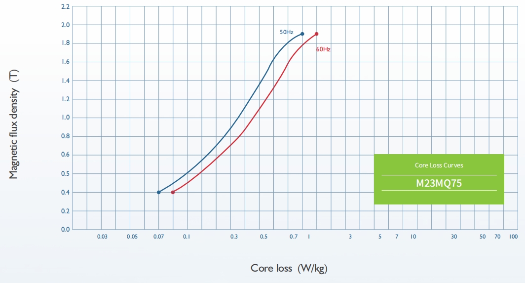
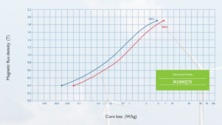
References Core Loss Curves
Applications
| Varieties | Conventional Grades | High Permeability Grades | Domain-Rened Grades |
| Large motors | √ | √ | |
| Large transformers | √ | √ | √ |
| Medium and small transformers | √ | √ | √ |
| Distributing transformers | √ | √ | |
| Voltage regulator | √ | √ | |
| Reactor and magnetic amplier | √ | √ | √ |
| IF transformer | √ | ||
| Mutual inductor | √ | √ | |
| TV transformer | √ | √ | |
| Radio transformer | √ | √ | |
| Radio broadcast transformer | √ |
Precision slitting, shearing, and professional step-lap/mitred lamination services
Based in Nantong, with advanced facilities including laser cutting and robotic stacking
Engineering support from drawing analysis to loss optimization and insulation strategies