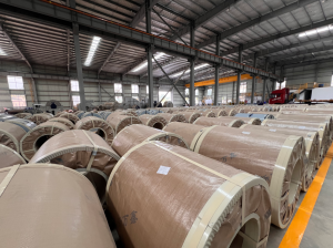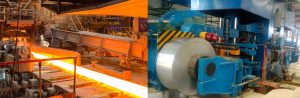
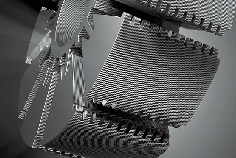
In the design and manufacturing of electric motors, the lamination of the core plays a decisive role. Have you ever wondered why motor cores are built using a laminated structure? The answer lies in efficiency. Laminated cores effectively suppress eddy current loss and, as a result, significantly improve motor performance. Although this might sound like a straightforward design choice, it actually involves complex processes and advanced materials. Through precision lamination of electrical steel sheets, the motor core achieves high performance and energy efficiency — forming the foundation for powerful and reliable machines.
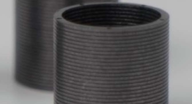
Consequently, this article will explore the most common motor core lamination methods and how each contributes to optimized performance across various applications. From traditional bonded laminations to modern laser-welded stacks, we will examine the technologies and benefits of each method, so that you can make informed decisions in motor core production.
Why Are Motor Cores Laminated?
How Eddy Currents Waste Energy
The primary reason is to reduce eddy current loss. When an alternating magnetic field passes through a solid core, it induces loop currents — called eddy currents — which lead to heat and wasted energy. Therefore, laminating the core with thin, insulated layers of silicon steel interrupts these current paths and minimizes losses.
CRGO vs. CRNGO: Picking the Right Electrical Steel
At MOOPEC, we offer two key types of electrical steel. First, CRGO (Cold Rolled Grain-Oriented Steel): with highly aligned grains along the rolling direction, CRGO offers high magnetic permeability and low core loss, making it ideal for transformers and high-precision motors. Second, CRNGO (Non-Grain-Oriented Steel): with uniform magnetic properties in all directions, CRNGO is perfect for rotating machines and compressors, since it strikes a balance between performance and cost.
In addition, our silicon steel comes with high-temperature-resistant insulation coatings (RoHS and REACH compliant), which not only suppress eddy currents but also ensure excellent formability. For instance, our CRGO grade M23MQ75 achieves core loss as low as 0.55 W/kg (P1.7/50) — a solid foundation for high-efficiency motors.
CRGO Grade Reference Table
Nominal Thickness(mm) | MOOPEC | Theoretical density (KG/dm³) | Min. Induction(T) | Min.Lamination factor(%) |
| 0.20 | M20G65 | 7.65 | 1.89 | 95.0 |
| 0.20 | M20G70 | 7.65 | 1.89 | 95.0 |
| 0.20 | M20G75 | 7.65 | 1.90 | 95.0 |
| 0.20 | M20G80 | 7.65 | 1.90 | 95.0 |
| 0.23 | M23G75 | 7.65 | 1.89 | 95.5 |
| 0.23 | M23G80 | 7.65 | 1.88 | 95.5 |
| 0.23 | M23G85 | 7.65 | 1.86 | 95.5 |
| 0.23 | M23G90 | 7.65 | 1.90 | 95.5 |
| 0.23 | M23G95 | 7.65 | 1.89 | 95.5 |
| 0.23 | M23G100 | 7.65 | 1.89 | 95.5 |
| 0.27 | M27G90 | 7.65 | 1.90 | 96.0 |
| 0.27 | M27G95 | 7.65 | 1.90 | 96.0 |
| 0.27 | M27G100 | 7.65 | 1.90 | 96.0 |
| 0.27 | M27G105 | 7.65 | 1.89 | 96.0 |
| 0.27 | M27G110 | 7.65 | 1.89 | 96.0 |
| 0.27 | M27G115 | 7.65 | 1.89 | 96.0 |
| 0.27 | M27G120 | 7.65 | 1.88 | 96.0 |
| 0.30 | M30G100 | 7.65 | 1.90 | 96.5 |
| 0.30 | M30G105 | 7.65 | 1.90 | 96.5 |
| 0.30 | M30G110 | 7.65 | 1.89 | 96.5 |
| 0.30 | M30G120 | 7.65 | 1.89 | 96.5 |
Meanwhile, if you would like to know more about how these grades are matched to specific motor designs, please feel free to contact us for the details.
What Are the Lamination Methods for Motor Cores?
There are four widely used lamination methods, and each one is suited to specific applications. Let’s walk through them one by one.
1. Bonded Lamination
Bonded lamination uses adhesive and heat curing to bond layers of silicon steel. Because it is tool-free, it is ideal for low-volume production and prototyping. Moreover, MOOPEC offers rapid sampling services based on your 2D/3D drawings.
2. Pinned Lamination
After drilling alignment holes, steel pins are inserted to hold the layers together. As a result, it is a reliable and mature method for mid-volume production, and it is commonly used in fans and automation motors. In addition, MOOPEC supports clients by designing pin layouts and supplying precision-cut blanks.
3. Interlock Lamination
Also known as in-die staking, this method uses V-shaped or dimpled embossments to lock sheets together during stamping. Consequently, it is suited to mass production of household appliances and power tools. While MOOPEC does not provide the stamping tools, we do supply high-precision sheets compatible with this method.
4. Laser Welded Lamination
This method is used in high-precision, small-size motor cores. Although MOOPEC does not offer welding, we supply laser-ready blanks with exact tolerances and welding gaps, which in turn reduces client processing complexity.
Which Method Fits Your Project?
Each method offers unique benefits depending on motor size, required precision, and production volume. Therefore, choosing the right lamination method ensures optimized cost, performance, and production efficiency.
Bonded vs. Interlock: Making the Right Choice
Selecting the best lamination process involves balancing three factors: tool cost, production speed, and dimensional accuracy.
On the one hand, bonded laminations require no tooling. As a result, MOOPEC offers 24-hour prototype delivery, which is perfect for R&D. On the other hand, interlock laminations do require tooling. However, MOOPEC partners with steel mills to offer co-developed materials and dies, sharing the initial tooling investment in order to lower unit costs in mass production.
Case in point: for a new EV motor project, MOOPEC supported a two-phase production — 100 prototypes via bonding, followed by mass production using interlock lamination. Ultimately, this approach cut total costs by 30%.
Is More Always Better?
Not necessarily. Lamination count depends on core height and sheet thickness; for example, a 60mm core needs roughly 170 layers of 0.35mm sheets. Moreover, more layers can increase cumulative errors, which in turn leads to uneven magnetic flux.
To control this, MOOPEC’s approach combines three safeguards:
- Material: CRGO/CRNGO with ±0.01mm thickness tolerance.
- Processing: Progressive die-stamping to maintain <0.05mm position deviation.
- Quality: SGS-certified insulation and stacking factor tests that ensure batch consistency.
The Machining Challenge
Post-lamination machining (for example, wire cutting or drilling) risks insulation damage and part deformation. Therefore, MOOPEC mitigates these risks in two ways.
- Pre-lamination machining: complex slots or holes are punched before bonding, which avoids secondary operations.
- Post-lamination machining: for interlocked cores, we provide custom fixtures and low-speed cutting to keep burrs under 5μm.
For instance, for a 300mm-diameter motor core, MOOPEC’s high-precision stamping achieved V-notch interlocking and 0.02mm roundness — without any secondary finishing.
From Drawing to Delivery: Real-World Cases
Case 1: Ultra-Thin Automotive Motor Cores
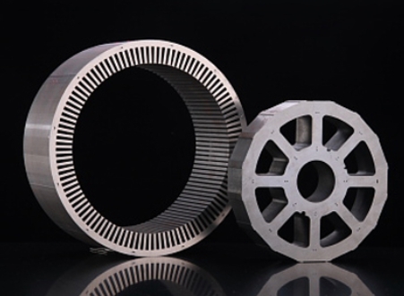
Automobile motor core
Faced with a need for corrosion-resistant cores, MOOPEC replaced the original steel with CRNGO and optimized tool parameters to keep burrs below 10μm. Meanwhile, our 24-hour sample turnaround helped the client reduce costs and speed up production.
Case 2: T-Shaped Cores for Industrial Drives
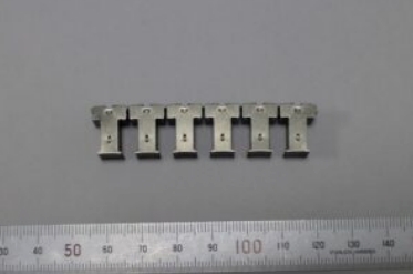
T-shaped laminated core
For a high-performance transmission project, MOOPEC used CRGO M23MQ75 and progressive die stamping to form multi-layer T-structures in one shot, with vertical accuracy under 0.05mm.
Case 3: Urgent Delivery for Appliance Stators
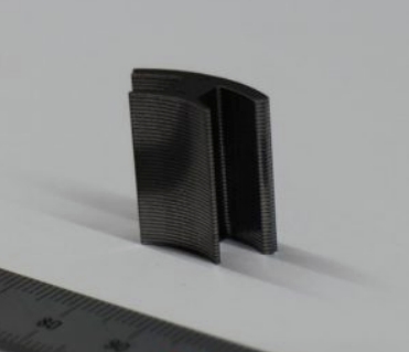
Split stator core
A sudden surge in demand required 5,000 stator cores within 15 days. In response, MOOPEC activated our flexible COPAD supply chain, from slitting and tooling to stacking assembly, thereby ensuring on-time delivery and full production continuity.
Why Choose MOOPEC?
- End-to-End Services: from steel selection to final core lamination — including cutting, forming, and testing.
- Global Delivery: Singapore HQ and multiple China plants for fast Asia-Pacific and Western fulfillment.
- Data-Driven: smart systems track order status, provide quality reports, and offer inventory advice.
At MOOPEC, we do more than supply steel — we provide a “Coil-to-Core” solution, letting you focus on design while we handle the complexity of materials and processing. Consequently, whether you are building 10 prototypes or producing 100,000 units, we deliver consistent, high-performance results every time.
Final Thoughts
In summary, motor core lamination is a refined intersection of material science and precision engineering. With 15 years of industry experience and a focus on CRGO/CRNGO processing, MOOPEC is proud to help global partners boost efficiency and reduce costs. Need help selecting a lamination method? Then let MOOPEC be your trusted lamination partner as we explore the future of efficient motors together.