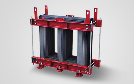
The magnetic circuit is a fundamental component of a transformer core. Whether laminated or wound, the core provides a low-reluctance path for the main magnetic flux generated by the excitation windings. The portion of the core surrounded by the windings is known as the core limb, while the part not enclosed is referred to as the yoke.
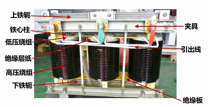 iron core
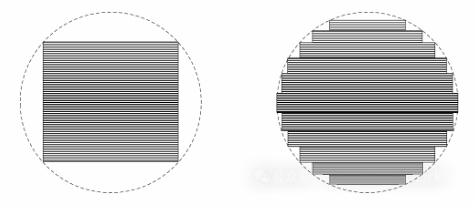
In small transformers, the cross-section of the core limb is typically rectangular or square. For large transformers, stepped polygonal cross-sections are preferred to approximate a circular shape and better accommodate the windings.
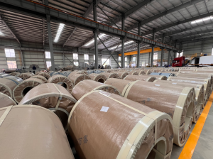
MOOPEC offers precision longitudinal and transverse cutting services for grain-oriented silicon steel, tailored to the structural requirements of both core-type and shell-type transformers. This ensures high assembly accuracy and material optimization for transformer manufacturers.
Core-Type vs. Shell-Type Transformer Structures
Core-type transformers have yokes positioned at the top and bottom of the windings but do not enclose the sides.
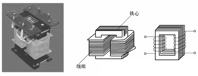
Shell-type transformers, by contrast, feature yokes that surround the top, bottom, and partially the sides of the windings.
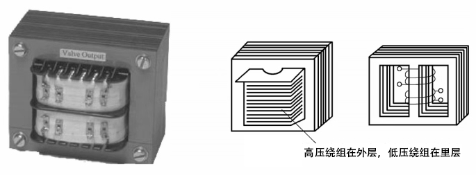
MOOPEC supports custom cutting of silicon steel laminations for both transformer types, including staggered overlaps and mitred joints, helping clients refine magnetic circuit performance.
Laminated Core Structures and Joint Techniques
Laminated cores are assembled using silicon steel sheets cut to specific profiles and stacked in layers. Most transformers use cold-rolled grain-oriented (CRGO) silicon steel, which exhibits lower losses and higher permeability along the rolling direction. Three-phase mitred core stacks are commonly adopted to reduce core loss at magnetic flux corners.
MOOPEC supplies premium CRGO materials in compliance with both domestic and international standards. Backed by high-precision cutting equipment, we support complex lamination geometries that guarantee superior magnetic performance and low core losses.
International CRGO Grades
| MOOPEC Grade | POSCO | JFE | TKS | NSC |
| M20MQ65 | ||||
| M20MQ70 | H070-20 | |||
| M20MQ75 | H075-25 | |||
| M20MQ80 | 20ZH80 | |||
| M23MQ75 | H075-23 | |||
| M23MQ80 | 23PHD080 | 23JGHE080 | H080-23 | |
| M23MQ85 | 23PHD085 | 23JGHE085 | H085-23 | 23ZH85 |
| M23MQ90 | 23PHD090 | 23JGH090 | H090-23 | 23ZH90 |
| M23MQ95 | 23JGH095 | 23ZH95 | ||
| M23MQ100 | 23JGH100 | 23ZH100 | ||
| M27MQ90 | 27PHD090 | 27JGSD090 | H090-27 | 27ZH90 |
| M27MQ95 | 27PHD095 | 27JGSD095 | H095-27 | 27ZH95 |
| M27MQ100 | 27PH100 | 27JGH100 | H100-27 | 27ZH100 |
| M27MQ105 | ||||
| M27MQ110 | 27JGH110 | H110-27 | 27ZH110 | |
| M30MQ100 | 30PHD100 | H100-30 | 30ZH100 | |
| M30MQ105 | 30PH105 | 30JGH105 | H105-30 | |
| M30MQ110 | H110-30 | 30ZH110 | ||
| M30MQ120 | 30PG105 | 30JGH120 | 30ZH120 |
Product Specifications
Nominal Thickness(mm) | MOOPEC | Theoretical density (KG/dm³) | Min. Induction(T) | Min.Lamination factor(%) |
| 0.20 | M20G65 | 7.65 | 1.89 | 95.0 |
| 0.20 | M20G70 | 7.65 | 1.89 | 95.0 |
| 0.20 | M20G75 | 7.65 | 1.90 | 95.0 |
| 0.20 | M20G80 | 7.65 | 1.90 | 95.0 |
| 0.23 | M23G75 | 7.65 | 1.89 | 95.5 |
| 0.23 | M23G80 | 7.65 | 1.88 | 95.5 |
| 0.23 | M23G85 | 7.65 | 1.86 | 95.5 |
| 0.23 | M23G90 | 7.65 | 1.90 | 95.5 |
| 0.23 | M23G95 | 7.65 | 1.89 | 95.5 |
| 0.23 | M23G100 | 7.65 | 1.89 | 95.5 |
| 0.27 | M27G90 | 7.65 | 1.90 | 96.0 |
| 0.27 | M27G95 | 7.65 | 1.90 | 96.0 |
| 0.27 | M27G100 | 7.65 | 1.90 | 96.0 |
| 0.27 | M27G105 | 7.65 | 1.89 | 96.0 |
| 0.27 | M27G110 | 7.65 | 1.89 | 96.0 |
| 0.27 | M27G115 | 7.65 | 1.89 | 96.0 |
| 0.27 | M27G120 | 7.65 | 1.88 | 96.0 |
| 0.30 | M30G100 | 7.65 | 1.90 | 96.5 |
| 0.30 | M30G105 | 7.65 | 1.90 | 96.5 |
| 0.30 | M30G110 | 7.65 | 1.89 | 96.5 |
| 0.30 | M30G120 | 7.65 | 1.89 | 96.5 |
Performance Comparison of Butt Joints, Miter Joints, and Step-Lap Joints
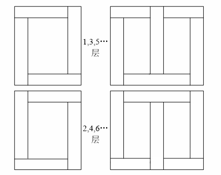
Double-layer Staggered Stacking of Rectangular Silicon Steel Laminations:
Miter-jointed Staggered Stacking of Silicon Steel Laminations:
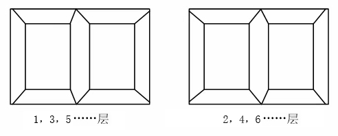
In this configuration, the air gaps between laminated sheets at the joint between the core column and the yoke are bridged by the overlapping laminations in the subsequent layer. As a result, when one layer is stacked over another, the joint area avoids continuous air gaps.
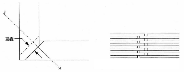
In a butt joint, the overlap angle is 90°, which is simpler to manufacture. However, since the magnetic flux at the joint does not follow the grain-oriented direction, it results in higher losses. Therefore, this type of joint is typically used in small transformers.
A miter joint usually features an overlap angle between 30° and 60°, allowing magnetic flux to pass along the grain-oriented direction, thereby minimizing losses.
The step-lap joint method provides superior performance compared to staggered joints.
In the diagram below, the operating magnetic flux density of the core is designed at 1.7 T. For the staggered lap core, the flux density at the joint rises to 2.7 T (deep magnetic saturation), while the flux density in the air gap is about 0.7 T. In contrast, for the step-lap core, the flux density in the air gap is approximately 0.04 T, and the flux density at the joint is close to 2.0 T.
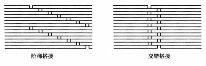 Step-lap and Staggered-lap Joints
MOOPEC provides silicon steel cutting services based on client drawings and can accurately process laminations for various joint styles, supporting quality optimization of transformer cores.
Optimizing Yoke Structures
In traditional core structures using yoke clamping rods, punched holes introduce magnetic distortion and elevate loss. Designs without tie rods perform better, utilizing special clamping methods (e.g., fiberglass or stainless-steel bands) and epoxy edge bonding to improve layer adhesion and reduce transformer noise.
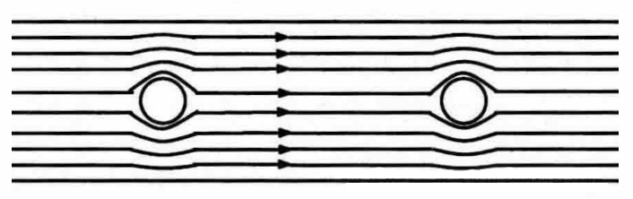
MOOPEC collaborates closely with clients to align lamination punching schemes with transformer design requirements, ensuring accuracy in cutting and improved core assembly.
Amorphous Alloy Transformers: Material Characteristics
Amorphous alloy transformers offer high permeability, low coercivity, and high saturation induction, with extremely low core losses. During processing, it’s essential to minimize mechanical stress to preserve magnetic stability.
MOOPEC operates dedicated cutting and stacking lines for amorphous alloy materials, ensuring consistent performance during processing and supporting the development of energy-efficient transformer designs.
Continuous Wound Core Technology
In planar wound core transformers, silicon steel is wound continuously without joints, significantly reducing magnetic reluctance. This structure reduces no-load current by 60–80% and no-load losses by 20–35% due to optimal grain orientation.
Post-annealing restores the magnetic properties lost during mechanical processing.
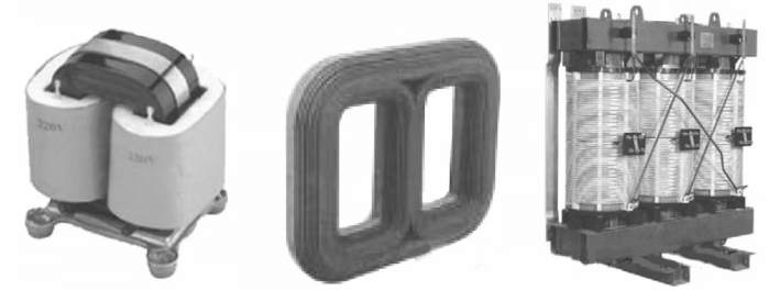
MOOPEC offers continuous core winding capabilities for multiple planar wound core specifications, maximizing the directional benefits of silicon steel to enhance core performance.
Advantages of Three-Dimensional Wound Core Technology
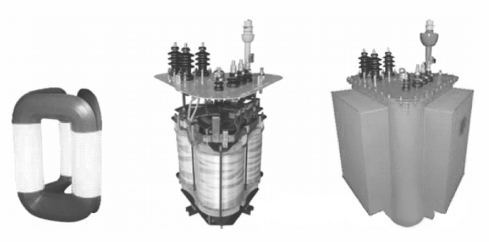
Three-dimensional wound core transformers feature a symmetrical magnetic circuit across all three phases, balancing no-load current. With magnetization aligned along the rolling direction and no overlaps between layers, magnetic flux is evenly distributed, avoiding localized saturation and flux distortion.
MOOPEC: Your End-to-End Expert in Electrical Steel and Precision Processing
As global energy efficiency standards continue to rise, so do expectations for transformer core materials and processing technology. MOOPEC is committed to providing high-performance electrical steels—both CRGO and amorphous alloys—along with comprehensive processing services, including:
✅ Grain-oriented silicon steel (CRGO) material supply
✅ High-precision slitting and shearing
✅ Custom lamination cutting
✅ Automated core winding (planar)
✅ Amorphous alloy cutting and stacking
✅ Flexible batch production support
Whether you’re developing high-efficiency power transformers or require reliable material processing services, MOOPEC delivers premium materials and precision-engineered solutions to help enhance your product competitiveness.