1. Material Consumption Analysis Under Identical Conditions
The Five Core Structures Compared
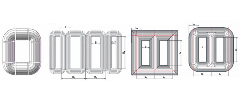
We selected five core structures for a horizontal comparison:
- Laminated core (circular cross-section)
- Laminated core (elliptical cross-section)
- Three-dimensional wound core
- Flat wound core
- Four-frame five-column wound core
The Uniform Conditions We Established
To facilitate analysis, we first established several uniform conditions:
- Identical effective core cross-sectional area
- Identical coil turn count
- Identical conductor wire size
Once these conditions are in place, designers can build transformers around the five core types. The results yield:
- Identical magnetic flux density in the cores
- Identical total height and thickness of the coils
- Identical window height and width of the cores
How We Calculated Weight and Perimeter
Next, we calculate the weight of the five core types under these parallel conditions. To aid understanding in the final comparison, we applied structural modifications and mathematical transformations to the core designs and calculations.
In addition, we calculated the perimeter of each core cross-section. Here the number of turns and the conductor wire’s cross-sectional area are the same. Therefore, the ratio of perimeters corresponds directly to material consumption and load losses of the coils. In fact, this relationship follows from the formula for coil weight Gcu = L × N × S.
2. Laminated Core (Circular Cross-Section)
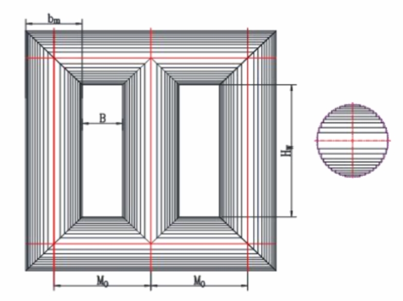
Schematic diagram of circular cross-section laminated iron core
Required Structural Analysis and Transformation
First, we cut the two side columns’ corners along the centerline of the upper and lower yokes. We then rotate these cut corners 180° around their midpoint, which forms two complete core columns (length = Hw + bm).
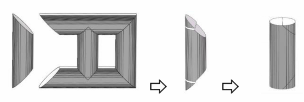 Side column transformation
Next, we apply a similar transformation to the upper and lower yokes. As a result, this step produces two flat-ended yokes (length = 2M0).
Then, we cut the middle column along the bottom of the upper yoke and the top of the lower yoke. Therefore, this step yields a complete core column (length = Hw).
Finally, we have not yet calculated the fusion areas between the columns and the yokes. In engineering calculations, we typically use the lamination width and step thickness of each layer to determine this value. For analytical calculations, however, we prefer a more streamlined method. For instance, integration using only the diameter and fill factor yields reasonably accurate results.
Therefore, we can transform the weight formula for the laminated core as follows:
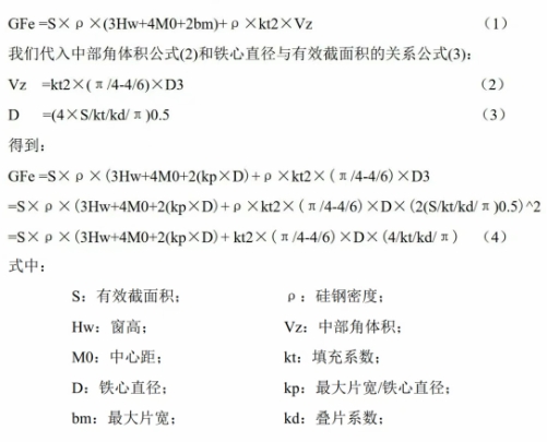
The weight formula for stacking iron cores
From the formula, we can see that only four parameters matter: S, Hw, M0, and D. For cross-type comparisons among the five core types, we must further reduce these four parameters into a single composite parameter. We will explain that step later.
Meanwhile, we also derive the formula for the perimeter of the circular cross-section of a laminated core: L = π × D.
3. Stacked Core (Long Circular Cross-Section)
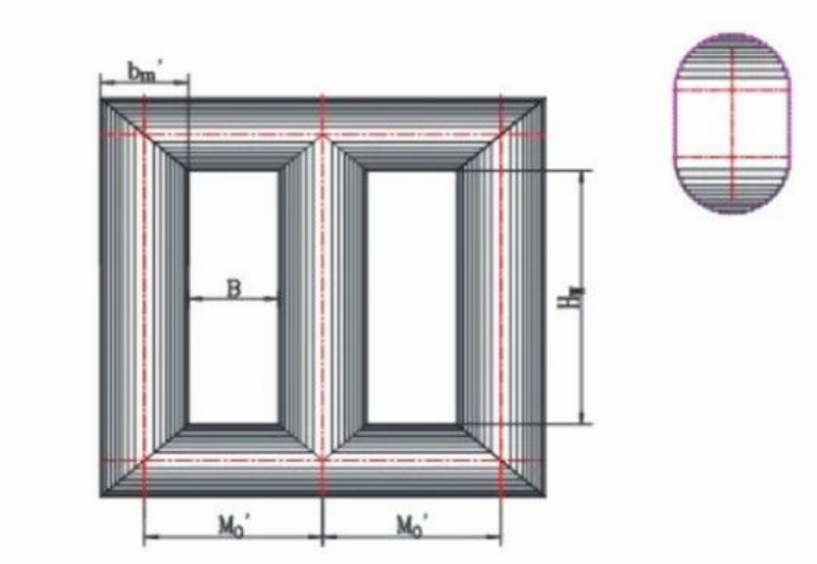
Design Concept
Before calculating the weight of this core type, let’s first understand its design concept. This core evolves from the circular-section laminated core. The transformation process involves multiplying the base circle by a reduction coefficient ks. Specifically, this step reduces the diameter and the maximum lamination width. It also thickens the maximum lamination layer to maintain the same core cross-sectional area.
As a result, this transformation shortens the M0 dimension of the core, which reduces core weight and no-load losses. However, it also increases the perimeter of the core cross-section, because a circle has the shortest perimeter for a given area.
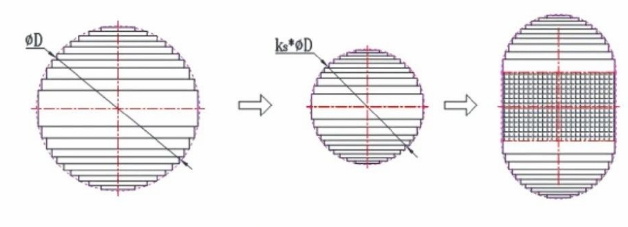
Illustration of the evolution of the long circular cross-section
Structural Transformation and Weight Formula
Similarly, we can apply the same transformation method described above. This gives us the weight formula of the laminated core with a long circular cross-section:
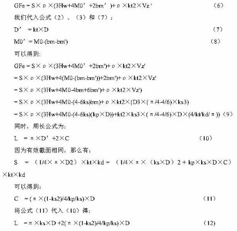
The weight formula of a laminated core with a long circular cross-section
4. Three-Dimensional Wound Core
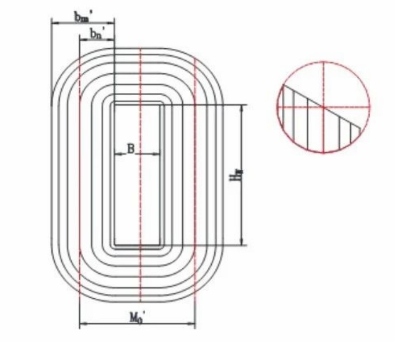
A single-frame illustration of a three-dimensional rolled iron core
Required Structural Analysis and Transformation
First, we cut a core frame along the four edges of its core window. As a result, this step gives us two core columns (length = Hw), two yokes (length = B), and four corner sections. We then calculate the weight of the four corner parts using integration, based on diameter and fill factor.
.
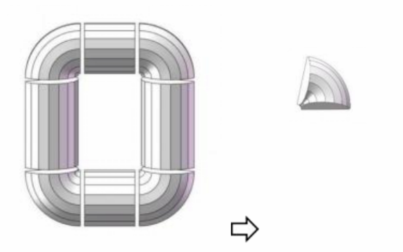 Calculation of the weight of the core of a three-dimensional coil
We can thus derive the weight formula for the three-dimensional wound core as:
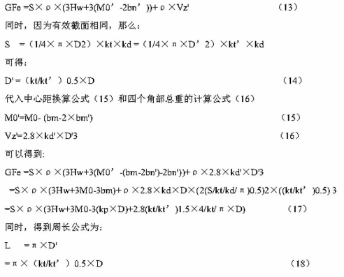
The weight formula for the three-dimensional wound core
5. Flat Wound Core
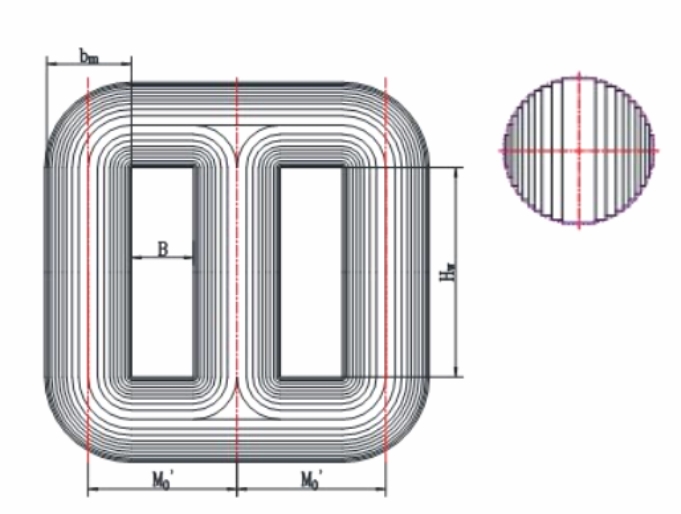
Illustration of the flat coiled iron core
Required Structural Analysis and Transformation
First, we cut the core frame along the four edges of two core windows. Consequently, this step yields three core columns (length = Hw), four yokes (length = B), two half-section yokes, and four corner parts of varying sizes.
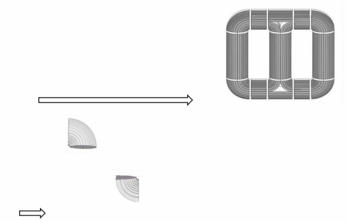 The principle of calculating the weight of three-dimensional coil cores
We can thus derive the weight formula for the flat wound core as:
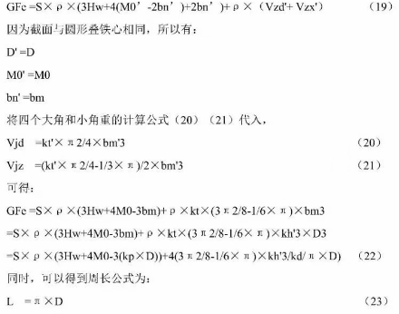
The weight formula for the flat wound core
6. Four-Frame Five-Column Wound Core
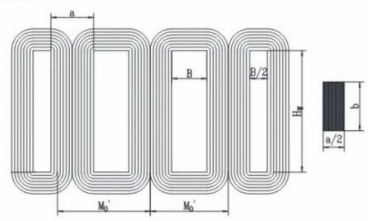
Required Structural Analysis and Transformation
The weight calculation for the four-frame five-column wound core is relatively straightforward. First, we multiply the cross-sectional area of a single frame (S/2) by the total central magnetic path length across all four frames. Thus, this step gives us the overall core volume.
Therefore, the weight formula for the core is:
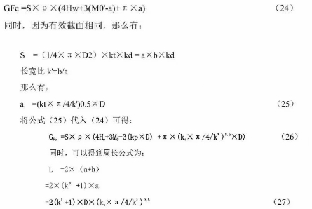
Weight formula for the core
7. Horizontal Comparison of the Five Core Types
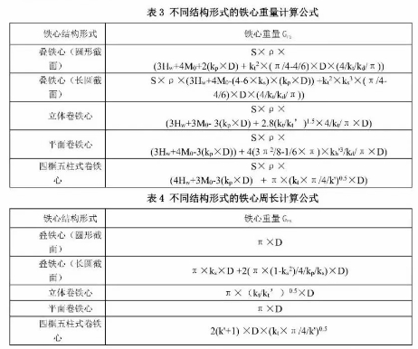
As the table shows, we can convert parameters such as Hw, M0, and D into a single variable. We then substitute the corresponding coefficients. In this way, we can perform a horizontal comparison of material consumption.
We then conducted numerical analysis on many distribution transformer designs with varying performance requirements. From that work, we selected three typical sets of Hw, M0, and D relationship values for substitution:
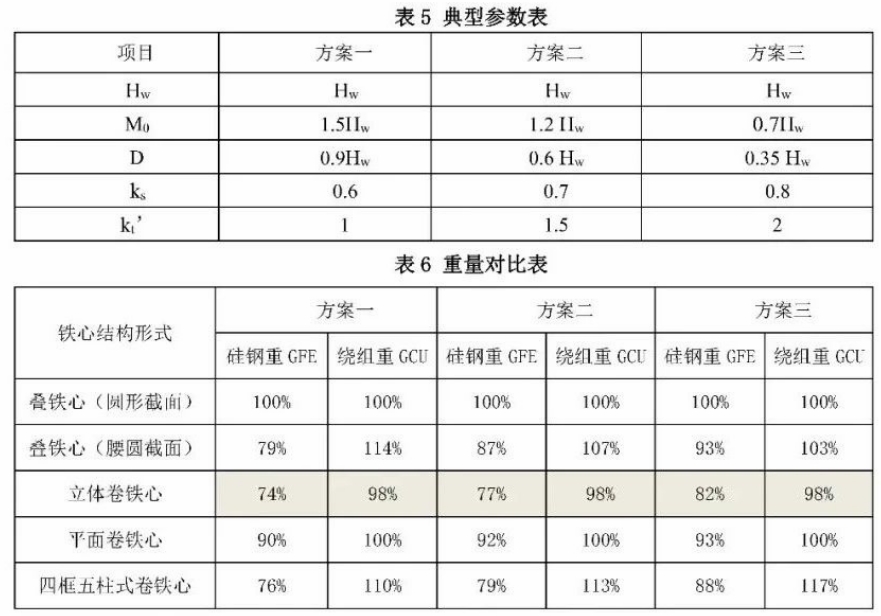
Parameter table
Note: For ease of comparison, all schemes adopt the same key design parameters. In actual design practice, however, designers can optimize any core structure type to achieve the most cost-effective solution.
Future Prospects of the Three-Dimensional Wound Core
The technology behind three-dimensional wound cores has matured significantly. The industry now has optimized production processes and standardized equipment and tooling systems. Thanks to its superior performance, cost-efficiency, and long-term energy savings, this design will likely become the mainstream solution in the transformer industry.
In recent years, national policies have accelerated the adoption of three-dimensional wound core technology. They recognize it as a green, low-carbon, and environmentally friendly transformer solution. As a result, various promotional catalogs across sectors now include it. As the power industry continues to push for sustainable innovation, this technology will lead a transformative shift in transformer design and manufacturing.
About MOOPEC
MOOPEC supplies high-quality electrical steel materials, including grain-oriented silicon steel (CRGO), tailored for transformer applications. With advanced slitting and lamination capabilities, we provide precision-cut core materials that meet the design requirements of both stacked and wound core transformers.
Our facilities support small-batch customization, rapid prototyping, and on-demand production. As a result, we are an ideal partner for transformer manufacturers seeking flexibility, speed, and quality. Headquartered in Singapore, MOOPEC serves global clients with end-to-end solutions, from material supply to core processing.
For more information, visit www.moopec.com. Alternatively, contact us directly to discuss how we can support your transformer projects.